If you are tired of load shedding problems and want to have a mini UPS system which can power up your home router for internet purposes and also charge your mobile phone then here is a circuit for you to do it yourself and get along with the load shedding problems.
The circuit provides an un-interrupted power supply (UPS) to operate 12V,9V and 5V DC-powered instruments at up to 1A current. Its not a pretty difficult circuit to make and the only expensive component in the whole circuit is the 12V battery.
Components Required:
- 12V (4.5 Ah) Battery
- 12-0-12 V , 1A Center Taped Transformer
- 4x 1N4007 Diode
- Zener Diode 10.5V (0.5W)
- Zener Diode 12V (1W)
- 3x LEDs (Red,White,White)
- 68 ohm Resistance (0.5W)
- 2x 1 Kohm Resistance
- 47 ohm Resistance (1W)
- 2x 390 ohm Resistance
- Pot 10 Kohm Variable Resistance
- Pot 22 Kohm Variable Resistance
- 470 uF Capacitor (25V)
- Transistor BC548
- Transistor TIP 127
- IC 7809
- IC 7805
- On/Off Switch
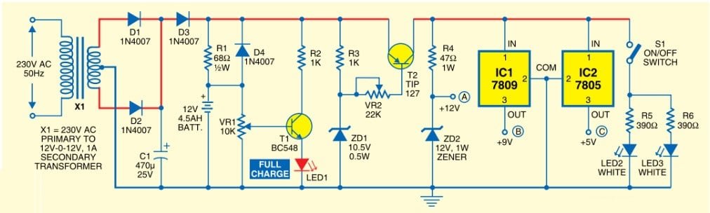
Circuit Diagram:
Working:
The backup battery takes up the load without spikes or delay when the mains power gets interrupted.It can also be used as a workbench power supply that provides 12V,9V and 5V operating voltages.The circuit immediately disconnects the load when the battery voltage reduces to 10.5V to prevent deep discharge of the battery.LED1 indication is provided to show the full charge voltage level of the battery. miniature white LEDs (LED2 and LED3) are used as emergency lamps during power failure at night.
A standard step-down transformer provides 12V of AC,which is rectified by diodes D1 and D2.Capacitor C1 provides ripple-free DC to charge the battery and to the remaining circuit.When the mains power is on,diode D3 gets forward biased to charge the battery.Resistor R1 limits the charging current.Potentiometer VR1 (10k) with transistor T1 acts as the voltage comparator to indicate the voltage level.VR1 is so adjusted that LED1 is in the ‘off’ mode when the battery is fully charged,LED1 glows indicating a full voltage level of 12V.
When the mains power fails,diode D3 gets reverse biased and D4 gets forward biased so that the battery can automatically take up the load without any delay.When the battery voltage or input voltage falls below 10.5V, a cut-off circuit is used to prevent deep discharging of the battery.Resistor R3, zener diode ZD1 (10.5V) and transistor T2 form the cut-off circuit. When the voltage level is above 10.5V,transistor T2 conducts and its base becomes negative (as set by R3, VR2 and ZD1).But when the voltage reduces below 10.5V,the zener diode stops conduction and the base voltage of transistor T2 becomes positive.It goes into the ‘cut-off’ mode and prevents the current in the output stage.Preset VR2 (22k) adjusts the voltage below 0.6V to make T2 work if the voltage is above 10.5V.
When power from the mains is available,all output voltages 12V,9V and 5V are ready to run the load.On the other hand,when the mains power is down,output voltages can run the load only when the battery is fully charged (as indicated by LED1).For the partially charged battery,only 9V and 5V are available.Also,no output is available when the voltage goes below 10.5V.If battery voltage varies between 10.5V and 13V,output at terminal A may also vary between 10.5V and 12V,when the UPS system is in battery mode.
Outputs at points B and C provide 9V and 5V,respectively,through regulator ICs (IC1 and IC2),while output A provides 12V through the zener diode.The emergency lamp uses two ultra-bright white LEDs (LED2 and LED3) with current limiting resistors R5 and R6.The lamp can be manually switched ‘on’ and ‘off’ by S1.
Precautions:
The circuit should be assembled on a general-purpose PCB or Vero Board.There must be adequate space between the components to avoid overlapping. Heat sinks for transistor T2 and regulator ICs (7809 and 7805) to dissipate heat must be used.
The positive and negative rails should be strong enough to handle high current. Before connecting the circuit to the battery and transformer,connect it to a variable power supply.Provide 12V DC and adjust VR1 till LED1 glows.After setting the high voltage level,reduce the voltage to 10.5V and adjust VR2 till the output trips off. After the settings are complete,remove the variable power supply and connect a fully-charged battery to the terminals and see that LED1 is on. After making all the adjustments connect the circuit to the battery and transformer.
You can now connect your internet router to the 12v supply and use the 5v output for charging your mobile phone.


can you give me its proteus pcb layout?
es ka input aur output voltage kitna ha???
5/9/12 V DC output. u can have all 3 outputs kindly refer to the circuit diagram